Cell Diagnostics
Understanding Gas Transport Resistances in Fuel-Cell Catalyst Layers
Polymer-electrolyte fuel cells (PEFCs) are emerging as a promising alternate energy source with applications in several sectors such as transportation. However, for PEFCs to be cost-competitive and achieve large scale commercialization, significant reductions of platinum loadings in PEFC catalyst layer is essential. Catalyst layers with low Pt loadings are associated with high transport loses which limit their maximum power output. We use a combination of multi-scale modeling and electrochemical techniques (limiting current measurements) to study the various transport loses in PEFC catalyst layers. Further, the impact of component material properties on the various transport loses is also explored.
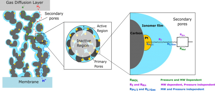
Figure at right: (Left) Qualitative illustration of reactant transport through the working electrode (WE). The reactant (red) diffuses through the pores, into and through the ionomer film (blue), and reacts at the Pt (yellow) catalyst site. Carbon particles are represented in black. (Center) Enlarged image of agglomerate coated by ionomer thin-film. The image highlights the active and inactive regions of the agglomerate at limiting current. (Right) The ionomer induced resistance includes of a series of ionomer and Pt nanoparticle interface resistances and permeation resistance within the ionomer thin-film. The gas-phase transport resistance in secondary pores is composed of both molecular and Knudsen transport.
Recent Publications (*equal contribution)
Tobias Schuler*, Anamika Chowdhury*, Anna T. Freiberg, Brian Sneed, Franz B. Spingler, Michael C. Tucker, Karren L. More, Clayton J. Radke, and Adam Z. Weber, “Fuel-Cell Catalyst-Layer Resistance via Hydrogen Limiting-Current Measurements”, Journal of The Electrochemical Society, 166 (7) F3020-F3031 (2019)
A. Chowdhury, C. J. Radke, and A. Z. Weber, “Transport Resistances in Fuel-Cell Catalyst Layers”, ECS Transactions, 80 (8) 321-333 (2017)
Redox Flow Battery Diagnostics
 Redox flow battery (RFB) technology is an ideal candidate for grid scale energy storage applications acting as the energy storage system for intermittent energy sources such as solar and wind. Additionally, RFBs are capable of decoupling energy and power which helps to size the cell to the immediate application. To date, RFBs remain susceptible to irreversible discharge due to crossover of ionic species and low electrolyte energy density. Overcoming the drawbacks of RFBs requires the exploration of advanced separator membrane chemistries, redox active species, electrode treatments, and the interactions of the liquid electrolyte with the separator membrane affect the overall cell performance. By conducting a series of in-situ cell test with ex-situ studies of membranes and electrolytes, insights are gained on improving RFB technology by increasing the electrochemical performance while reducing active species crossover.
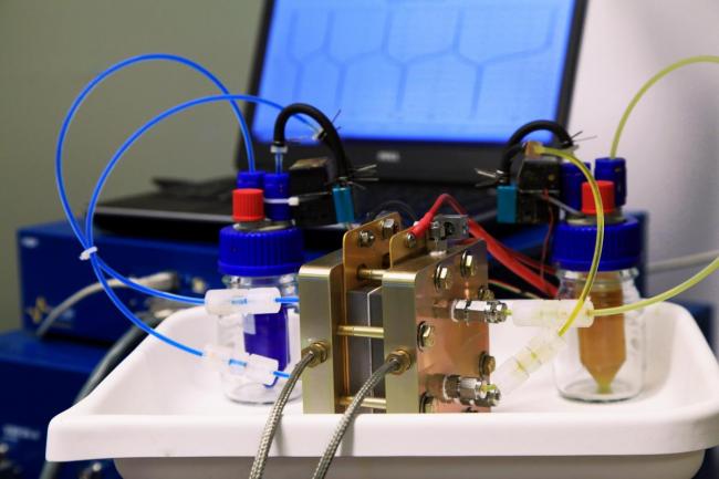
Figure at right: Lab scale redox flow battery with liquid electrolytes flowing in each electrode. Each liquid chamber is separated by a polymer membrane, acting as a solid electrolyte, that prevents crossover of liquid electrolyte.
Hydrocarbon Oxidation
With a growing abundance of light alkanes, a better utilization is required to convert these light hydrocarbons into higher valued partial oxidation product. One way to do this is leveraging electrolysis architecture and electrochemically oxidize these light alkanes. Current goals in this area are understanding the kinetic pathways and optimizing the membrane electrode assembly to selectivity obtain the desired products. We are exploring different catalysts, conditions (pH, water content, temperature, etc), and reactant gases to achieve this goal. By fabricating new membrane electrode assemblies, electrochemically testing, and real-time detection of the products formed, insight into electrochemical C-H bond activation is guiding the design of the cell and catalyst synthesis.
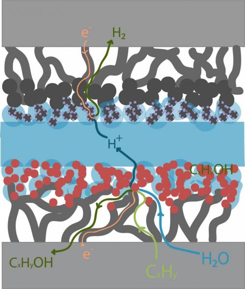
Figure at right: Generalized flows for a membrane electrode assembly is shown. The membrane electrode assembly (MEA) comprised of a proton-exchange membrane, anode and cathode catalyst layers, and gas diffusion layers help transport the gases to the reactive sites and provide conductivity for electrons and ions. Hydrocarbon oxidation processes are gas phase reactions that depend on water vapor as the oxidant, so both reactants must be able to reach the catalyst sites, as depicted.
Electrochemical Reduction of CO2 in Membrane-Electrode Assemblies
The electrochemical conversion of CO2 has the potential to achieve greenhouse gas emission mitigation coupled with the production of value-added fuels and chemicals, allowing us to simultaneously achieve intermittent renewable energy storage and carbon-neutrality. Key in actualizing this is the development of an optimized CO2 reduction device that can selectively produce C2+ products such as ethylene and ethanol at commercially-relevant current densities. We are studying membrane-electrode assemblies (MEAs) in order to elucidate the unique mass-transfer, kinetic, and ohmic limitations of this system for efficient and selective CO2 reduction. We fabricate and characterize MEAs and conduct systematic and fundamental electrochemical experiments under various temperature, relative humidity, materials fabrication, cell assembly, and feed purity conditions in order to measure and understand the performance and limitations of this complex system, specifically in the catalyst-ionomer-membrane environment.
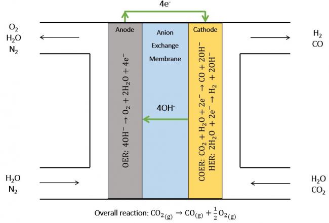
Figure at right: A vapor-fed Full-MEA (membrane-electrode assembly) for CO2 reduction. Humidified gases are fed into the anode and cathode and, with the application of an overpotential, the OER (oxygen evolution), HER (hydrogen evolution), and COER (carbon monoxide evolution) electrochemical reactions are facilitated in the catalyst layers, leading to the release of product gases. Each electrode consists of an appropriate electrocatalyst, ionomer, and gas-diffusion or porous transport layer, with a selective AEM (anion exchange membrane) in between.