Fuel Cells
Modeling Synergistic Degradation Phenomena in PEFC Membranes
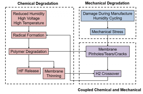
During operation, polymer-electrolyte fuel cells (PEFCs) are subjected to mechanical and chemical stressors that contribute to membrane degradation, performance loss, and eventual failure. Together, synergistic effects between mechanical and chemical degradation mechanisms lead to accelerated degradation. This project aims to develop a physics-based model to understand the synergistic effects of chemical and mechanical degradation and the coupled nature of performance and durability in PEFCs. The modeling work has incorporated pinhole growth effects as well as the use of cerium as a chemical scavenger to mitigate chemical degradation.
Figure at right: Key physical phenomena driving coupled chemical and mechanical membrane degradation in PEFCs during operation.
Recent Publications:
V.M. Ehlinger, A. Kusoglu, A.Z. Weber. Modeling Coupled Durability and Performance in Polymer-Electrolyte Fuel Cells: Membrane Effects. Journal of The Electrochemical Society 166 (7), F3255-F3267
Modeling Transport in High Surface Area Carbon Supports
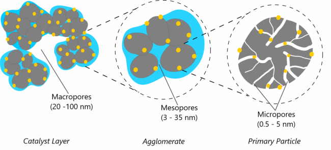 Carbon supports form the primary porous structure of catalyst layers in which Pt particles are deposited and ionomer films are distributed. Previous studies have demonstrated that the carbon-support significantly influences PEFC performance and stability. Unlike non-porous carbon supports, high surface area carbon support has micropores in the interior of carbon particles where Pt particles can deposit. Growth and coalescence of Pt nanoparticles within the HSC micropores is restricted due to small pore sizes, thus providing greater stability. However, the small pore size also restricts ionomer penetration. The interior Pt particles thus rely on condensed/adsorbed water pathways for proton conduction. We use modeling to study water uptake and Pt utilization in catalyst layers with high-surface-area carbon support.
Figure at right: Schematic representation of pores in HSC based CL. Carbon particles are shown in grey, Pt particles in yellow and ionomer is presented in blue.
Recent Publications:
A Chowdhury, R. M. Darling, C. J. Radke and A. Z. Weber, “Modeling Water Uptake and Pt Utilization in High Surface Area Carbon”, ECS Transactions (Submitted)
Performance Modeling of PEM Fuel Cells
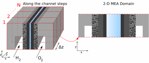
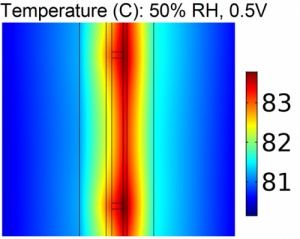
Modeling Proton Exchange Membrane (PEM) fuel cells provides an efficient method for analysis and diagnostics. This project is focused on developing macro-scale, multi-phase and multi-physics models of PEM fuel cells. We are specially interested in using physics-based models to understand along the channel effects of hydration, reactant depletion and heat generation on cell performance. The model is also used for rapid diagnostics of cell degradation and to analyze effects of degradation on performance.
Figures at right: A schematic of along the channel pseudo 3-D cell model utilizing a detailed 2-D model combined with a stepping algorithm.
Recent Publications:
L. M. Pant, Z. Yang, M. L. Perry, and A. Z. Weber. “Development of a Simple and Rapid Diagnostic Method for Polymer-Electrolyte Fuel Cells”. Journal of the Electrochemical Society, 165(6), F3007-F3014. 2018
Modeling Anion-Exchange Membrane Fuel Cells
 Anion-exchange membrane (AEM) fuel cells, like their more common proton-exchange membrane counterparts, use hydrogen and oxygen to produce electricity. AEM fuel cells typically use a hydroxide-conducting membrane, rather than a proton-conducting membrane, which allows the use of less expensive catalyst materials.
Our AEM fuel cell modeling work focuses on improving two main drawbacks of AEM fuel cells. First, because of the alkaline environment in AEM fuel cells, the half-reactions for hydrogen oxidation and oxygen reduction are slightly different, resulting in water production at the anode and consumption at the cathode. Thus, traditional water-management strategies for PEM fuel cells are not as effective in AEM fuel cells. We simulate and study water transport through AEM fuel cells to understand and optimize water management in these cells.
Second, carbon dioxide in the atmosphere reacts with hydroxide in the AEM, resulting in voltage losses and system inefficiency. We study carbon dioxide and carbonate transport within the AEM fuel cell as well, to understand the mechanism of this voltage loss and devise mitigation strategies.
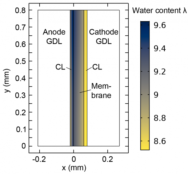
Figure at right: Diagram depicting high water concentration at the anode (blue) and low concentration at the cathode (yellow) in an AEM fuel cell.
Recent Publications:
Gerhardt, Michael R, Lalit M Pant, and Adam Z Weber. "Along-the-Channel Impacts of Water Management and Carbon-Dioxide Contamination in Hydroxide-Exchange-Membrane Fuel Cells: A Modeling Study." Journal of The Electrochemical Society 166.7 (2019) F3180 - F3192.